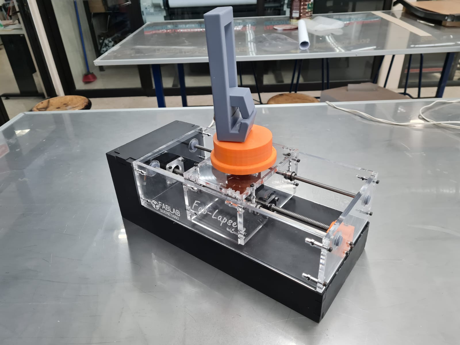
Hero Shot
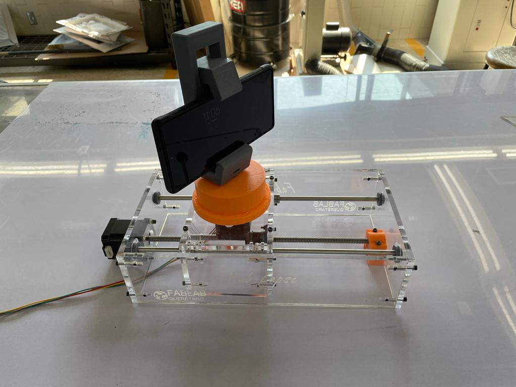
This is Fab-Lapse, a mechanical camera slider designed to create 360° time-lapse videos. It features a 12" linear stage, as well as a 360°+ freely rotating phone mount.
The Machine is made from 6mm acrylic as well as 9mm MDF base to house the electronics.
We developed a custom PCB using an ATTiny84 as well as two Pololu A4988 Stepper Drivers to control two NEMA 17 motors.
The Machine can easily record interesting timelapse sequences, using common phone recording equipment.
The machine features a linear stage with an endless screw. The linear stage moves a phone mount car that sits on linear bearings and has a NEMA 17 motor that rotates a 3dprinted phone mount.
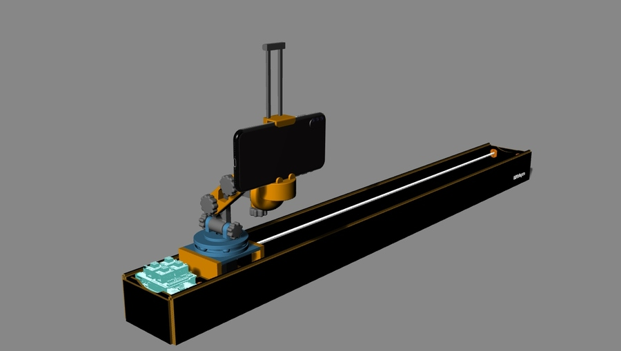
We still don't have lab access, so for this week we remotely designed a Camera Dolly, there were several iterations, and we had a hard time on the osurcing of parts. We weren't sure if they'd be here on time, so parts were tossed around. If we had been on the lab, we could have been more executive on this. However, we are happy that we have a model for our machine, and it looks rather fine.
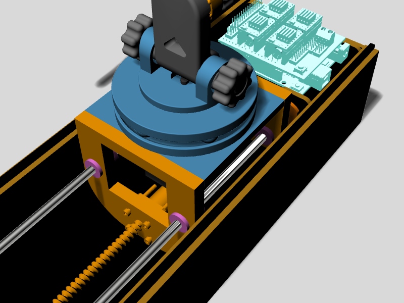
This is the final model.
We have a linear stage that moves a car box on round guide shafts, on this car, there is a NEMA 17 motor rotating a 3d printed bearing with a telescopic camera mount. I modeledd the bearing assembly for mounting the camera phone stand.
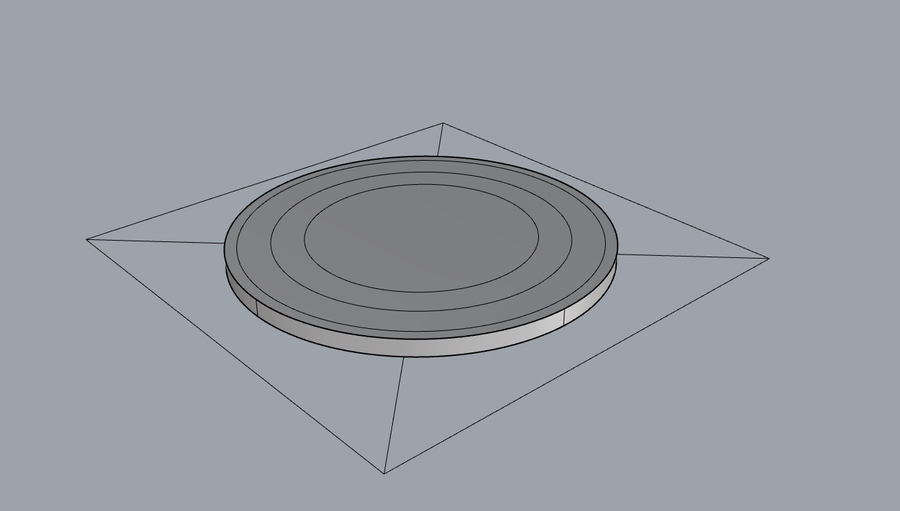
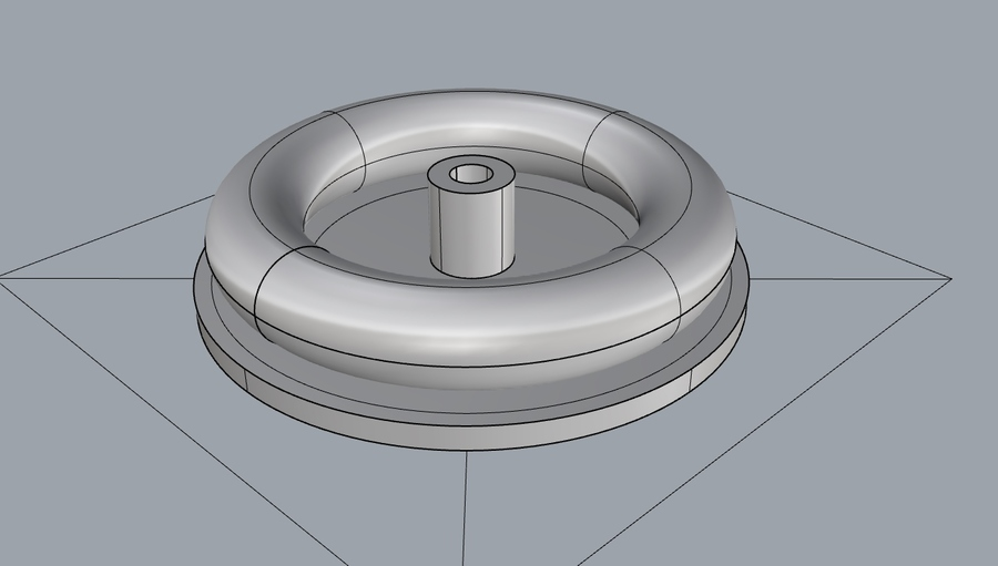
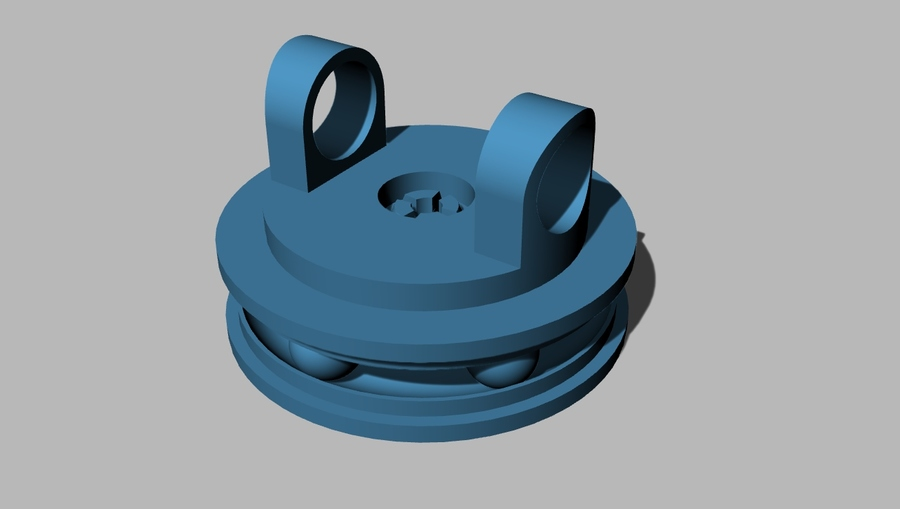
The bearing assembly will have some marbles or 3d printed spheres to roll around, I started with something like aplate or disk to provide the rolling surface.
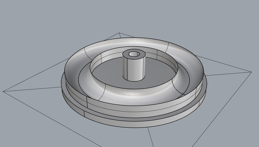
I modelled a torus that represents the marbles rolling, and the I subtracted that volume from another disc, this gave me a toroidal half pipe. After this, it was a matter of creating the corresponding surface on top. I also checked for ultra thin surfaces and modeled them out.
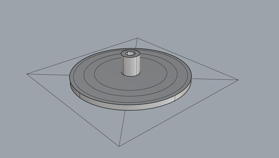
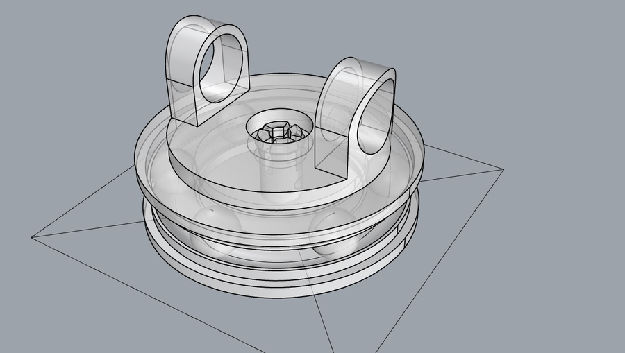
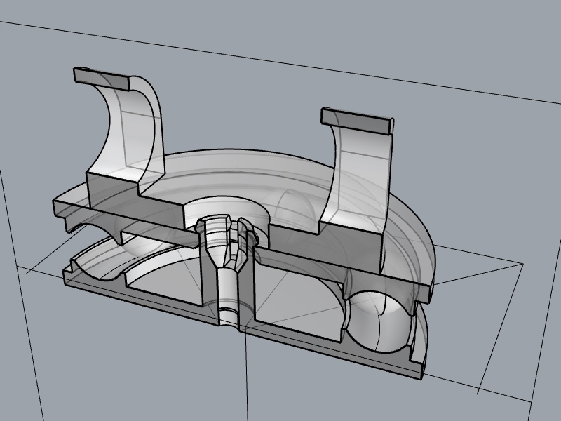
I came up with a snappung joint to keep the top disc in place while the marbles rotate. This snapping joint is also a bushing where the motor shaft will be locked.
This is how it looks on the final model.
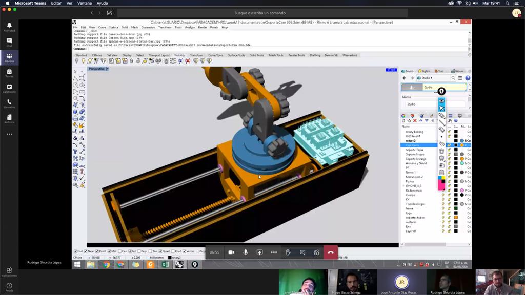
This is us discussing our design on Microsoft Teams, our remote meeting point, we had several of these rounds as wou'll see on the group page.
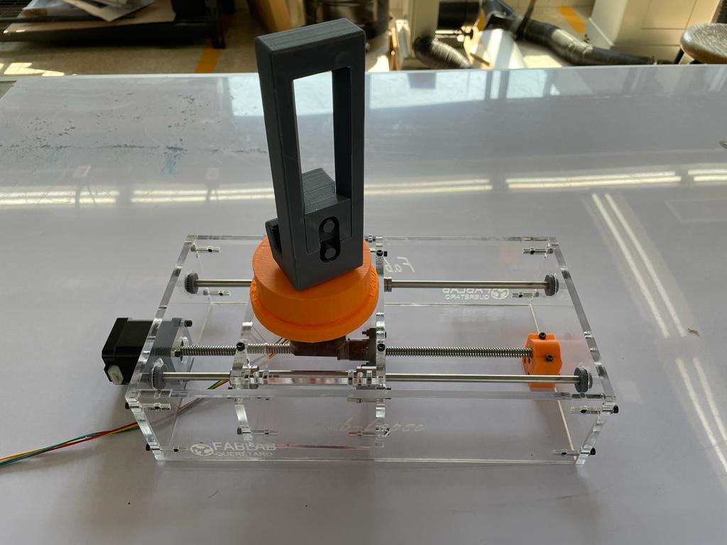
Final Machine Design
We finally made the machine out of acrylic. The stage was made with a NEMA17 Stepper with integrated screw, and the rotation of the camera phone was a simple NEMA 17.
This is the machine without the phone:
And this is the machine with a phone mounted on it:
The first part is to actuate it manually, I think it moves smoothly, but the linear bearings need something to hold them in place:
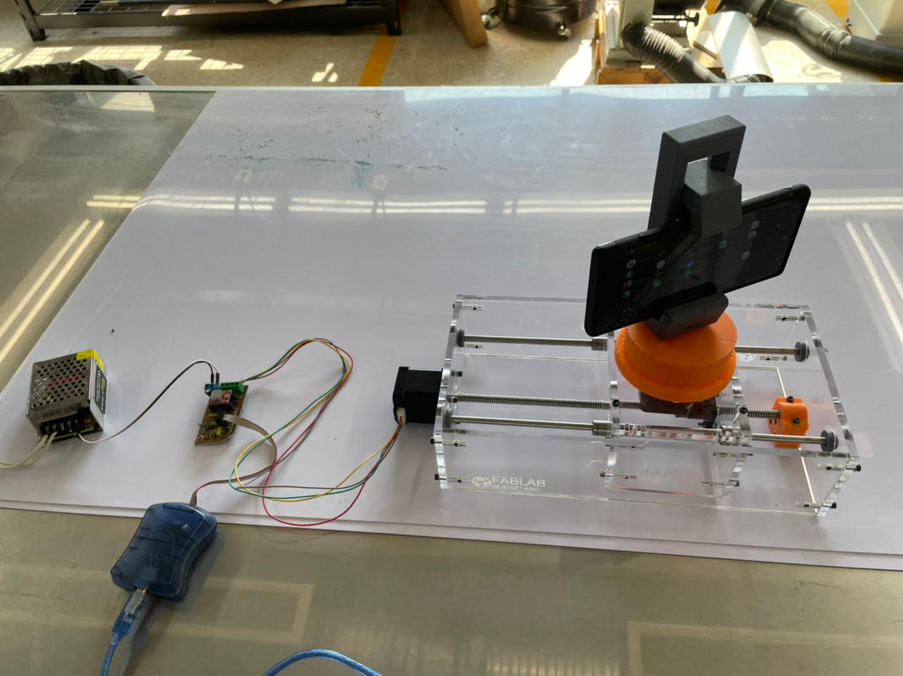
Next we need to actuate both motors independently. We used the board from my final project for now, but we will design a new board to control both motors.
This is the basic setup for this round of tests, you can see the stepper board, as well as the programmer we are using to control it:
Here is the actuated linear motor:
The second motor needs more tweaking on the speed settings. Here it is with a very slow speed, basically one 1.8° step a second:
When it goes faster it is crazy fast, so we started to experiment with microstepping which is supported by the Pololu A4988 that we are using:
However, when you actually do the timelapse, the stepping is not that bad, and the vibration is something that we need to adress:
Electronics
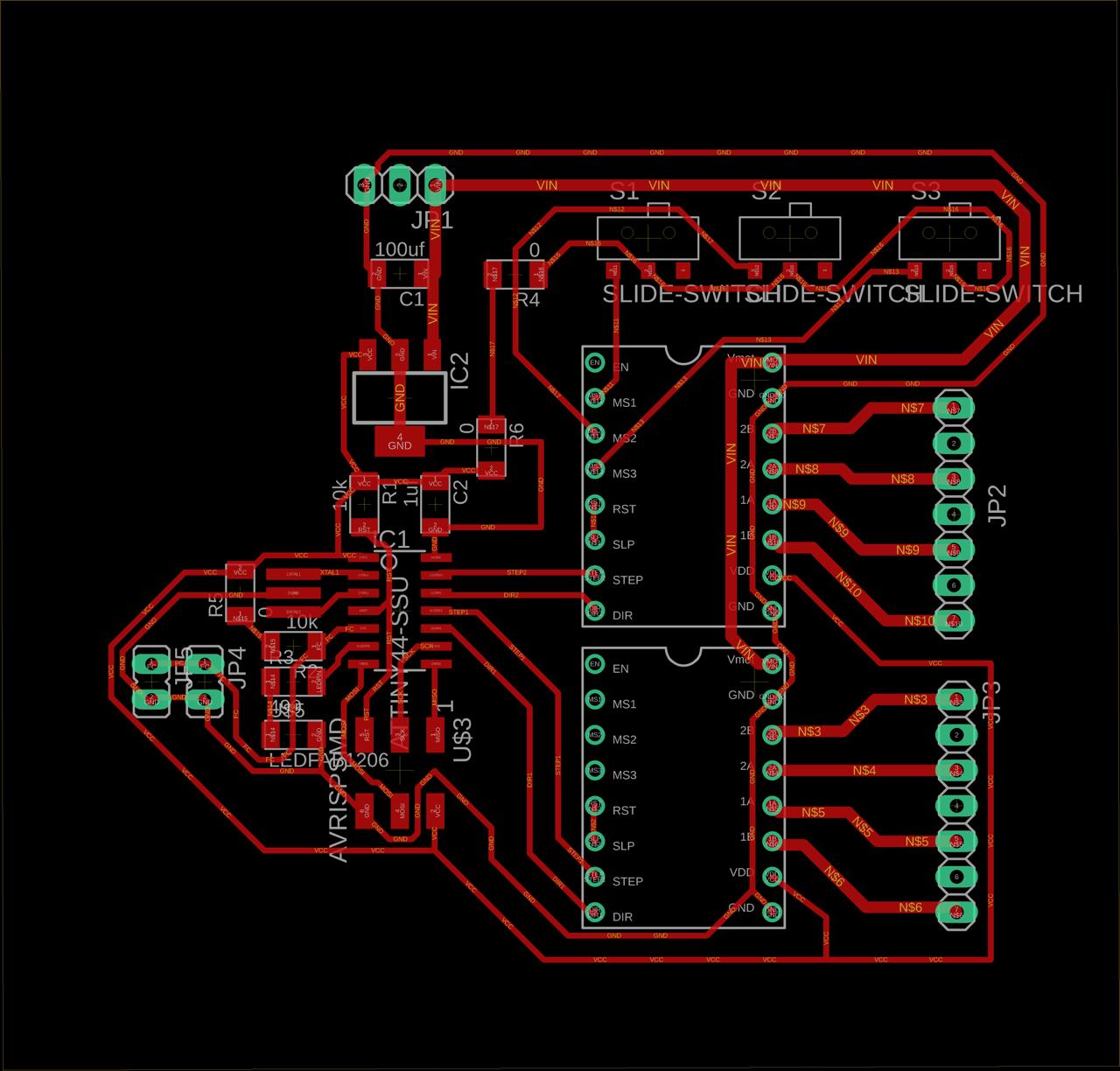
Our Machine is controlled with a custom PCB. that uses an ATTiny84 to send pulses to two Pololu A4988 stepper driver breakout boards.
My most significant contribution to the group project was the design and programming of the electronics that will drive it. I designed the board based on my final project board.
This is the board components:
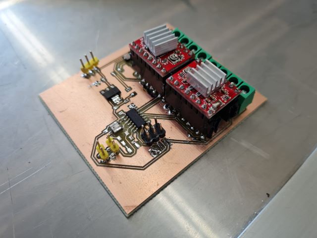
This is the final board:
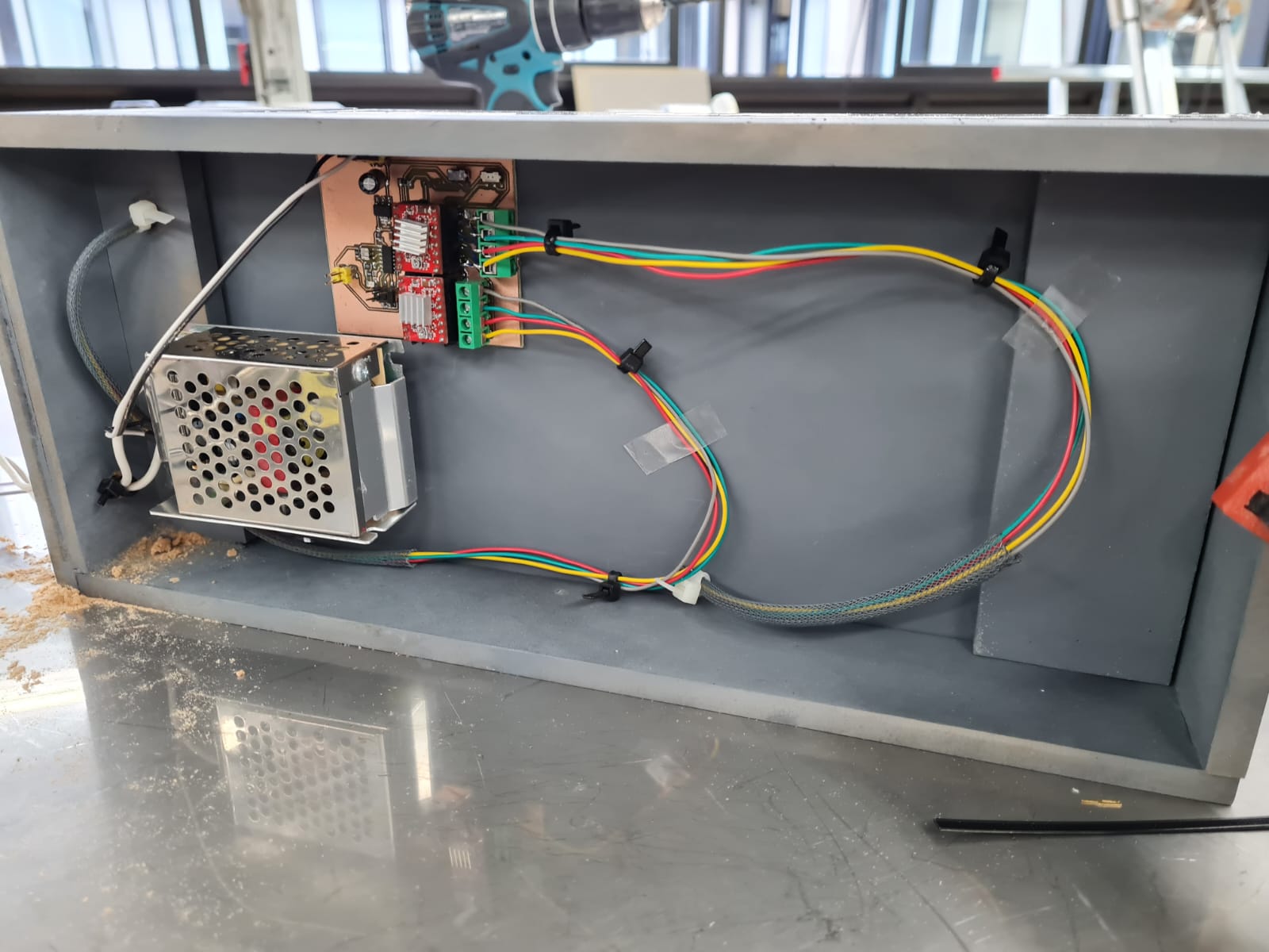
This is the final board in the machine base housing:
One of the most interesting parts, was the development we had to make on the microstepping of the phone mount motor. As explained earlier, the phone mount vibrated a lot when dealing with low speeds of 1 step/second.
The Pololu A4988 supports microstepping which basically is a way for the motor to move less than the 1.8°/step that is a full step.
In order to use this feature, you have to send a HIGH signal to the microstepping inputs of the driver.
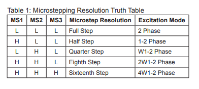
As seen on the datasheet, the three inputs are named MS1, MS2 and MS3. However you set these inputs, according to the datasheet, will result on the microstepping ratio, from 1/2 step to 1/16th step. This means that at half step, you'll get 1.8/2 degrees per pulse, resuklting in less motion per pulse, which at lower speeds, helped reduce the vibration considerably.
Since we didn't have any pins left on the ATTiny84, we decided to just hard code it into the board using slide switchesusing the slide switches.
Here is the code that we used to run it. It's important to note the relationship between the rotations. The steppers we are using do 1.8° per step at full step.
Linear Stage:
Full step
1.8° per step
8mm per revolution (screw diameter)
carriage length: 240mm
200 steps per revolution
step delay: 7000 microseconds=0.007sec
1.4 sec per revolution
42 sec total time at 7000 microseconds step delay
Phone Mount:
sixteenth step
0.1125° per step
3200 steps per revolution
step delay: 13,125 microseconds=0.013125sec
42 sec per revolution
42 sec total time at 0.013125 microseconds step delay
from this information we can get a relationship of 7,000/13,125 to calculate the relationship between the two stages.
this means that we need a step on the phone mount every 1.87 steps of the linear stage. So what we did is to get a roughly 2 to 1 relationship.
Thus, here is the code:
                        //ATTiny84 running two Pololu stepper drivers
                        //Written by Rodrigo Shiordia for Fabacademy
                        //Machine Design

                        int pulPin1 = 2,  dirPin1 = 3;
                        int pulPin2 = 0, dirPin2 = 1;
                        int stepDelay = 7000;
                        int ledPin = 7;
                        int dir = 0 ;
                        int count = 0;

                        void setup() {
                          // put your setup code here, to run once:
                          pinMode(pulPin1, OUTPUT);
                          pinMode(dirPin1, OUTPUT);
                          pinMode(pulPin2, OUTPUT);
                          pinMode(dirPin2, OUTPUT);
                          pinMode(ledPin, OUTPUT);
                        }

                        void loop() {
                          digitalWrite(ledPin, HIGH);
                          digitalWrite(dirPin1, dir);
                          digitalWrite(dirPin2, dir);
                          digitalWrite(pulPin1, LOW);
                          if (count % 2 == 0) {
                            digitalWrite(pulPin2, LOW);
                          }
                          delayMicroseconds(stepDelay);
                          digitalWrite(pulPin1, HIGH);
                          if (count % 2 == 0) {
                            digitalWrite(pulPin2, HIGH);
                          }
                          delayMicroseconds(stepDelay);
                          count++;
                        }